Oleopneumatic shock struts use hydraulic fluid, compressed gas, and darn clever engineering to improve our landings.
If every one of our landings were a “greaser” and if runways never had bumps or potholes, then the landing gear on our airplanes could be dead simple. Wheel assemblies rigidly attached to the airframe would work fine, just as they did on the toy wagon and roller-skates I had when I was a kid.
In the real world, some landings (“arrivals”?) involve embarrassingly firm touchdowns. Some of the runways and taxiways we use are not exactly pool-table smooth, either. That’s why nearly every airplane ever built has been equipped with a shock-absorbing landing gear designed to survive considerable abuse.
Lightweight aircraft can often get away with a simple spring-loaded gear. Many older designs (like the venerable Piper Cub) use a simple hinged gear leg with stranded rubber cords used to absorb the shock of landing. Mooneys use a stack of shock-absorbing rubber doughnuts for the same purpose.

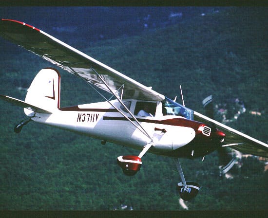
Many aircraft, notably Cessna singles, use shock-absorbing spring steel gear legs, an elegantly simple design pioneered and patented in the 1930s by air racer Steve Wittman. Cessna licensed the design from Wittman in the 1940s, introduced it in 1946 on the Cessna 140 (Figure 1), and has used it on its single-engine aircraft ever since. Some recent lightplane designs (e.g., Cirrus SR20/SR22) employ a similar spring-leg approach using composites instead of steel.
Recoil
Spring-type landing gear designs like these have some compelling advantages when used in light planes. They’re cheap, lightweight, require few parts, and are essentially maintenance-free. Rubber shock cords and doughnuts require periodic replacement, but Wittman-type spring-steel gear legs often last the life of the airframe with zero maintenance.
Unfortunately, spring-type gear designs also have two significant disadvantages. First, they don’t scale well to heavier aircraft. As the weight of the aircraft increases, the size of the rubber or steel or composite springs required to absorb the shock of landing tends to get impractically large.
Second, and perhaps more important, spring-type gear legs aren’t very good at damping the recoil of a hard landing. The harder the landing, the more energy the landing gear springs absorb, and the more energetic the ensuing recoil. The result is that a hard landing on a spring-type gear often results in a bounced landing—which at best can be embarrassing, and at worst can result in loss of control and damage to the aircraft.
Consider Charles Lindbergh’s historic New-York-to-Paris flight on May 20-21, 1927. His custom-built Ryan NYP monoplane was adapted from Ryan’s M-2 Mailplane, which used a shock-cord-type landing gear like most aircraft of its day. But the custom-built NYP carried 450 gallons of fuel and had a maximum takeoff weight of 5,250 pounds—nearly twice that of the M-2. The gear of the NYP still used shock cords, but was massively beefed up to support the additional weight.
The result was obvious to anyone who has seen the old motion picture footage of Lindberg’s takeoff from Roosevelt Field, N.Y., and his landing at Le Bourget Field, Paris. The takeoff was a heart-stopping sequence of bounces, and the landing was also badly bounced. Both were fine examples of the recoil problem inherent in spring-type landing gear designs. As aircraft got larger and heavier, a more forgiving landing gear design became a necessity.
Enter the oleo

The answer was the oleopneumatic or “air-oil” shock strut, originally introduced in the late 1920s by the Cleveland Pneumatic Company. Cleveland’s “Aerol” strut quickly gained acceptance in the 1930s, and was the landing gear technology of choice by the time aviation exploded in the 1940s, transforming Cleveland Pneumatic Aerol into one of the nation’s largest wartime industrial companies.
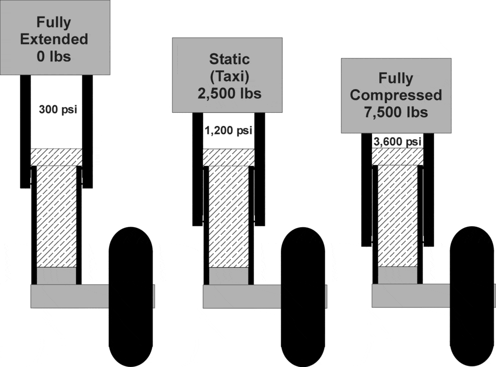
The “oleo” strut uses compressed gas combined with hydraulic fluid to absorb and dissipate the shock of landing, and to damp the recoil to minimize bounced landings. The strut consists of two telescoping tubes with externally closed ends (Figure 2). The upper tube is historically referred to as the “cylinder” and the lower tube as the “piston.” The telescoping tubes form a variable-displacement chamber that contains hydraulic fluid on the bottom and compressed air or nitrogen on the top. As the strut is compressed during landing, the incompressible hydraulic fluid maintains constant volume, while the gas at the top of the strut is compressed to smaller volume and higher pressure. The compressed gas acts as a spring, and performs the same function as the shock cord or spring steel of a spring-type gear.
The bottom of the upper tube (“cylinder”) is equipped with a high-pressure seal to prevent fluid or gas from escaping from the chamber as the strut compresses and extends. For light-duty struts, the seal may be a simple O-ring; for heavier-duty struts, it tends to get a bit more exotic. Just below the seal is a scraper ring to prevent dirt from damaging the seal as the strut compresses. The seal and scraper ring are typically retained by a snap ring.
Taming the bounce

The purpose of the hydraulic fluid in an oleo strut is to damp the action of the gas “spring,” slowing the rate at which the strut absorbs landing shocks, and slowing the post-impact recoil to minimize the chance of a bounced landing.
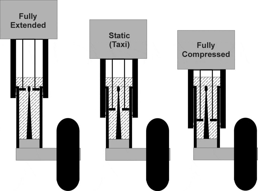
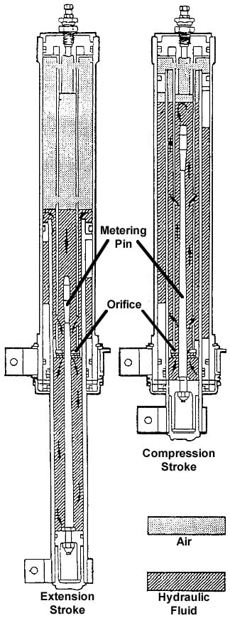
To accomplish this, the strut is equipped with an orifice plate that divides the lower fluid-bearing part of the strut into two chambers (Figure 3). As the strut compresses during landing, the fluid is forced through the orifice from the lower chamber to the upper one, and as the strut extends during post-landing recoil (or takeoff), the fluid is forced back through the orifice in the opposite direction. The size of the orifice and the viscosity of the fluid limits the rate at which the strut can compress or extend.
Now here’s where things get really clever: Most oleo struts employ a tapered “metering pin” to vary the size of the orifice and therefore the rate of fluid flow from one chamber to the other. The more the strut compresses, the smaller the orifice becomes, and the more resistant the strut is to compress or extend. The result is a landing gear that starts off very soft at touchdown, and becomes increasing stiff as the strut compresses and the energy of landing is dissipated. When near-fully compressed after landing, the strut is highly damped and recoils slowly and with great reluctance.
While the metering pin gradually tapers from bottom to top, it normally has a larger-diameter “bulb” at its extreme upper end. The purpose of this odd-looking swelling is to slow the extension of the strut on takeoff just as it reaches full extension, thus slowing strut extension just before hits its mechanical stop after liftoff.
Designing a strut
A widely-used rule-of-thumb is that the compression ratio of a main-gear oleo strut should be about 4:1 between the fully-extended and static (taxi) position, and about 3:1 between the static and fully-compressed position.

The latter figure comes from FAA certification requirements, which require that a landing gear be designed to handle a hard landing with a sink rate of 10 feet/second (or 600 FPM). A simple calculation shows that for a main landing gear strut with a typical maximum throw length of 12 inches, the required deceleration from such a landing is about 3Gs. Thus, the strut needs to be able to dissipate a worst-case landing force equivalent to about three times the aircraft’s normal static weight.
There are other constraints on gas pressure. If the minimum pressure in the strut when fully extended is less than about 50 psi, the O-ring seal at the bottom of the cylinder may not seal tightly enough against the piston to prevent the strut from leaking. Conversely, if the maximum pressure in the strut when fully compressed is more than 5,000 psi, the seal might blow out on a hard landing. Finally, if the pressure in the strut in its normal static position is more than about 1,500 psi, it will be impossible to add gas to the strut without jacking the aircraft (since nitrogen bottles typically have a maximum pressure of 1,800 psi when full).
Given these constraints, a working pressure of about 1,200 psi under static (taxi) load is a good compromise. At full extension (with a 4:1 compression ratio), the pressure drops to about 300 psi, and at full compression (with a 3:1 compression ratio), the pressure rises to about 3,600 psi—easily within the necessary constraints.
The required strut diameter can be easily determined based on the weight of the aircraft. For example, my Cessna T310R has a maximum weight of about 5,500 pounds, which means that each main gear needs to support roughly 2,500 pounds under static conditions (with the nose gear supporting a bit as well). At 1,200 psi, this requires a main gear piston cross-sectional area of a bit over 2 square inches, which translates into a piston diameter of about 1.7 inches.
The fully-extended main gear on my T310R has a throw of about 12 inches. At a 4:1 compression ratio, the static extension is about three inches. In a hard-landing scenario—say I forgot to flare and drove the airplane on at a 600 FPM sink rate—the strut would theoretically compress to about one-inch extension with an internal pressure of 3,600 psi (3:1 ratio) and an opposing force of 7,500 pounds.
A typical nosegear oleo on a tricycle-gear airplane handles a lot less weight than the mains, and has a shorter throw and lower working pressure. But its ability to dampen landing shocks with minimal recoil is perhaps even more important than for a main gear. Consider that a nosegear recoil pitches the nose up, increases the wing angle-of-attack, causes the airplane to want to start flying again—and can easily lead to divergent pitch oscillations (often referred to as “PIO” or “pilot-induced oscillations”) that have been known to wrinkle firewalls, curl prop tips, snap off nosewheels, and generally give owners a bad hair day.
That’s probably the principal reason that although tricycle-gear Cessna singles still use the simple Wittman-type spring gear for their mains, they use an oleo strut on the nose.
Strut inflation
Your aircraft’s service manual provides detailed servicing instructions for your oleos. Typically, a specific inflation pressure is given for servicing the strut when it is fully extended (i.e., airplane on jacks), and a strut-extension measurement is given for “airing up” the strut with the aircraft “on its feet.” These servicing instructions are also contained on an FAA-required placard affixed to each strut. For example, the main gear struts on my airplane are placarded for a no-load inflation pressure of 320 psi, and for a static-load extension of three inches. For the nose strut, the corresponding figures are about 50 psi and 1.5 inches.
But be careful: If you notice that your strut extension is a bit lower than it should be, the temptation is to “air up” the strut a bit (using a nitrogen bottle or strut pump) to bring it back up to the specified height. But before you do this, stop and think about it for a moment. How do you know whether the strut extension is low because it needs more air/nitrogen pressure, or whether it’s low because it needs more hydraulic fluid?
If the strut is actually low on fluid (because some seeped out past the O-ring seal between the cylinder and piston) and you compensate by adding air/nitrogen, then what you’ve done is to lower the compression ratio between static and fully-compressed positions of the strut. Repeat this a few times and you might wind up with a strut that’s sufficiently short on fluid and long on air that it’ll physically bottom out on a hard landing—and that could get expensive.
Remember, the function of gas in an oleo is to provide the strut’s spring force, and the function of hydraulic fluid is to provide the strut’s damping force. A useful test is to rock the aircraft up-and-down and see how the strut reacts. If the strut bounces up and down freely with relatively little damping, then it’s most likely low on fluid. If the strut moves stiffly and shows little willingness to bounce, the fluid level is probably adequate and the strut may just need a little air or nitrogen.
If there’s any indication that the strut may be low on fluid (i.e., it’s “bouncy”), you should definitely check the fluid level in order to preclude the possibility of damage during a firm landing. Low fluid is a potentially a lot more serious than low air. Incidentally, the most likely time for a strut to lose fluid is in frigid temperatures, so be especially vigilant during the wintertime.
Servicing
To service an oleo strut with fluid, jack the aircraft until the the wheel is off the ground. Open the fill valve located at or near the top of the strut to fully deflate the strut.
Once the strut is deflated, attach one end of some clear plastic tubing to the filler valve, and immerse the other end of the tubing into a pan of MIL-H-5606 hydraulic fluid. Slowly pump the strut up and down a number of times. Each time you extend the strut, it will suck fluid up the tube and into the strut. Each time you compress it, it will expel gas that is entrapped in the fluid (plus excess fluid) into the pan. Continue pumping until you’ve eliminated as much entrapped gas as you can, and the expelled fluid comes out relatively free of bubbles.
At that point, compress the strut fully once more (to eject excess fluid), then disconnect the plastic tube. Extend the strut fully, and then service the strut with either nitrogen or dry compressed air to the recommended pressure. Close the filler valve and install its protective cap.
After the strut has been serviced, remove the aircraft from jacks, rock the just-serviced strut up and down, and check that the strut extension is reasonably close to the static extension values given in the service manual and on the strut placard. A little variation is okay, but if the strut is significantly under or over the recommended static extension, you might consider adding or removing a little air or nitrogen.
You bought a plane to fly it, not stress over maintenance.
At Savvy Aviation, we believe you shouldn’t have to navigate the complexities of aircraft maintenance alone. And you definitely shouldn’t be surprised when your shop’s invoice arrives.
Savvy Aviation isn’t a maintenance shop – we empower you with the knowledge and expert consultation you need to be in control of your own maintenance events – so your shop takes directives (not gives them). Whatever your maintenance needs, Savvy has a perfect plan for you: