Basics of piston aircraft engine fuel metering systems
If you fly a piston aircraft, chances are it has a spark-ignition (SI) engines that burns gasoline. There also exist compression-ignition (CI) engines—also called diesels—that burn kerosene, but in today’s GA fleet they’re still few and far between. While CI engines spray liquid fuel at high pressure directly into the combustion chambers, SI engines combine air and gasoline together to form a combustible air-fuel charge that is ingested into the combustion chambers and then ignited electrically by spark plugs.
To be combustible, the charge must have an air-fuel ratio between 8-to-1 and 18-to-1 by weight. Anything less than 8-to-1 is too rich to burn, and anything more than 18-to-1 is too lean to burn. The chemically perfect mixture—what a chemist would call “stoichiometric”—has an air-fuel ratio of about 15-to-1 by weight, and the mixtures we actually use when flying tend to be fairly close to that ratio.
The process of creating a combustible charge with the desired air-fuel ratio is called “metering” and it’s not as easy as it sounds. The hard part is to keep the air-fuel ratio constant at all power settings and altitudes, and to do so in a fashion that doesn’t impose unacceptable workload on the pilot.
Carburetors
The traditional way to accomplish this is with a carburetor. The word derives from the French verb carburer (to combine with carbon); more specifically, in the context of engines, it means to increase the carbon content of air by mixing it with a volatile hydrocarbon.
The earliest carburetors were developed in the 1860s and used drips, wicks, and various other mechanisms for combining fuel and air. These “evaporative carburetors” relied on evaporation of volatile fuel into the air passing through them. They didn’t work very well unless the engine operated at a constant RPM and power setting. Notable among these was a design German engineer Wilhelm Maybach that introduced the float-and-needle-valve mechanism most commonly used in contemporary carburetors, Maybach’s carb was used by Karl Benz’s 1897 “Patentwagen.”
The early 20th century brought the development of “proportioning carburetors” capable of measuring the volume of air flowing into the engine and determining the proper amount of fuel required to create the desired air-fuel ratio across a wide range of engine speeds and loads. Numerous such designs were developed—Claudel-Hobson, Beardmore, Zenith, Bendix-Stromberg—but the one most commonly found in piston GA airplanes is the Marvel-Schebler aircraft carburetor, invented by George Schebler and Burt Pierce and originally used in Indy racing cars from 1911 to 1935. Their Marvel-Schebler Carburetor Company changed ownership numerous times—Borg-Warner, Facet Aerospace, Zenith Fuel Systems, Precision Airmotive, Volaré Carburetors—and finally emerged as Marvel-Schebler Aircraft Carburetors, LLC in 2011.
The Marvel carb

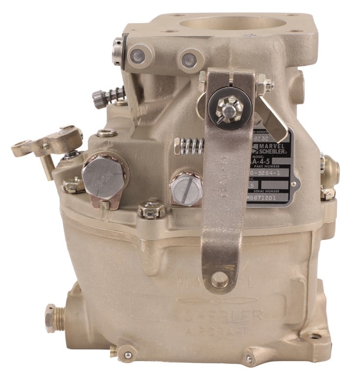
Marvel-Schebler MA-4-5 updraft carburetor
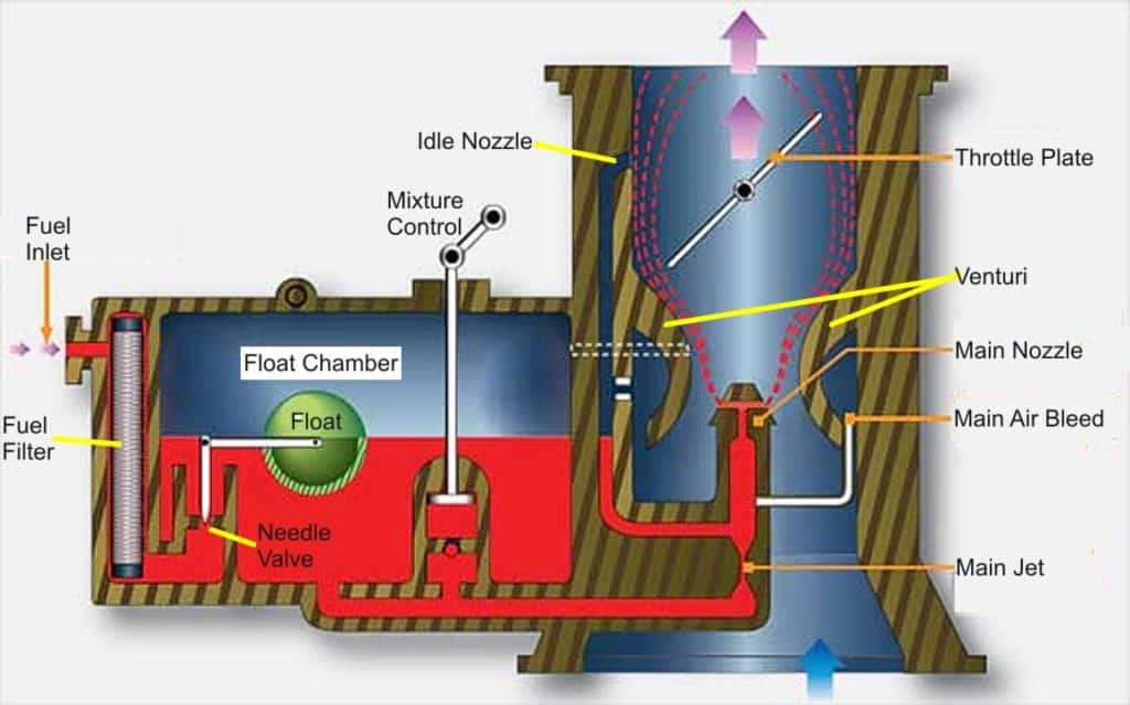
The basic design of the Marvel carb is simple. It has two main sections: a float chamber and a throttle body. The float chamber is a fuel reservoir that works a lot like the tank on a flush toilet. Fuel enters the float chamber through a filter and a needle valve. As the float chamber fills with fuel, the float rises and closes the needle valve, shutting off the fuel supply once the fuel level reaches the desired level. As the carb draws fuel from the float chamber, the float drops and opens the needle valve to admit more fuel into the float chamber.
The engine ingests air through the throttle body, which contains a controllable throttle butterfly plate that regulates airflow into the engine according to the position of the cockpit throttle control. Most Marvel carbs are MA-series “updraft” carburetors where air flows from bottom to top (designed to mount below the engine), but some are HA-series “sidedraft” units where airflow is horizontal (designed to mount behind it). Except for throttle body orientation, both series are quite similar.

Diagram of float-type carburetor
The throttle body contains a venturi through which the induction air passes before it reaches the throttle butterfly. Thanks to Bernoulli’s principle, the venture causes the air’s velocity to increase and its pressure to decrease. The greater the volume of airflow through the throttle body, the more the air pressure decreases inside the venture.
A fuel discharge nozzle fed from the float chamber has its tip strategically positioned in the center of the venturi. The pressure drop (suction) generated by the venturi causes fuel to be sprayed by this nozzle into the airflow, where it is atomized into a mist of tiny droplets. The greater the airflow, the greater the suction, and therefore the greater the fuel flow discharged by the nozzle. (This is what makes the carb “proportioning.”)
A few complications
This simple scheme works fine at most power settings. However, when the throttle is closed and the engine is at idle, there’s so little airflow and so little venturi suction that the main nozzle won’t provide enough fuel to keep the engine running. Consequently, the carb has a special “idle circuit” that feeds extra fuel to a secondary nozzle located just downstream of the throttle butterfly and allows the idling engine to suck additional fuel into the airstream to provide smooth idling. This idle circuit has a needle valve adjustment that allows the idle mixture to be fine-tuned.
Another complication occurs when the throttle is advanced rapidly from idle to high power (e.g., at takeoff or go-around). The airflow increases immediately, but it takes awhile for the increased fuel flow to reach the cylinders, and that can cause the engine to hiccup at throttle-up. The solution is to add a throttle-operated “accelerator pump” to the carb to inject a bolus of extra fuel through the main nozzle to prevent the engine from stumbling. Some carbs also have a “power enrichment valve” or “economizer circuit” that provides an extra-rich mixture at wide-open throttle.
Yet another difficulty involves changes of altitude. The carb’s venturi effect produces a fuel flow proportional to airflow volume, but the engine needs an optimum air-fuel ratio by weight, not volume. As the aircraft climbs higher and the density of air decreases, the weight of the induction air decreases even though its volume remains constant, causing the mixture to get progressively richer. The usual solution is to provide a cockpit mixture control that allows the pilot to lean the mixture as necessary as the aircraft climbs. (A few fancy carburetors—mostly on big radial engines—incorporate an aneroid-operated “auto-lean” mechanism to eliminate the need for manual leaning, but most don’t.)
Throttle body injection
Float-type carburetors have some inherent limitations. One is that they don’t work properly in inverted flight or other negative-G situations. Another is that they’re quite susceptible to ice build-up in the venturi and on the throttle butterfly caused by the sharp temperature drop caused by evaporation of the fuel. Also, it’s tricky to get them to work with turbocharged engines.
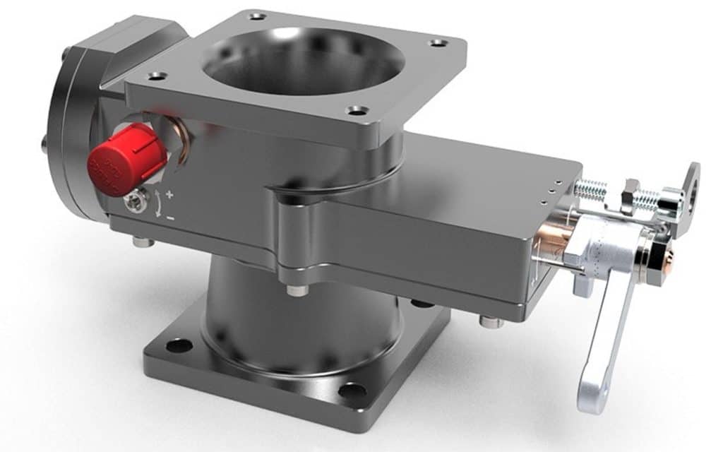
One way to solve these problems is to reposition the main nozzle downstream of the throttle butterfly instead of upstream, and use carefully regulated fuel pressure (instead of venturi suction) to meter the fuel sprayed by the nozzle. Such a device is known as a “pressure carburetor” or alternatively “throttle body injection” (TBI).

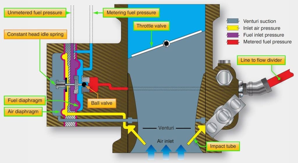
The Bendix-Stromberg pressure carburetor is mostly found on big radial recip engines. It uses a clever four-chamber regulator to meter the proper amount of fuel to its downstream discharge nozzle. Chambers A and B contain air, and are separated by a diaphragm. Chamber A contains pressurized air from “impact tubes” (essentially tiny pitot tubes) in the throttle body, while chamber B contains suction from the venturi. The pressure difference between A and B varies with airflow through the throttle body, and generates a force on a rod that controls fuel flow to the nozzle. Similarly, chambers C and D contain fuel, and are separated by another diapragm. Chamber D contains pressurized fuel from the fuel pump, while chamber C contains lower-pressure fuel after it has passed through a metering orifice. The pressure difference between D and C varies with fuel flow to the nozzle, and generates an opposing force on the control rod. Equilibrium is reached when the airflow force and the fuel flow force are identical, and that occurs when the air-fuel mixture is optimal.

Vastly simpler throttle body injection designs from Ellison and Rotec have become quite popular among owners of experimental amateur-built airplanes, particularly ones used for aerobatics where conventional float-type carbs don’t do so well.
Intake port injection
Whether float-type or TBI, carburetors create an air-fuel mixture at the throttle body, and it then must travel through complex induction plumbing to reach the individual cylinders. Because air turns corners more readily than fuel droplets, a certain amount of centrifugal separation invariably occurs, resulting in different cylinders receiving slightly different air-fuel ratios. To achieve an even mixture distribution among the cylinders, it’s better to inject metered fuel directly into the cylinders’ intake ports. In today’s GA fleet, the two most common systems for doing that are Bendix-RSA fuel injection and Continental Motors fuel injection.

The Bendix-RSA system—used on all fuel-injected Lycomings and a few Continentals—uses a throttle body and four-chamber fuel metering servo that’s nearly identical to the one used by the Bendix-Stromberg pressure carburetor. The principal difference is that the throttle body doesn’t have a fuel discharge nozzle. Instead, metered fuel from the servo is routed to a flow divider that divides the fuel into four or six equal fractions and routes them to fuel discharge nozzles threaded into the intake ports of the individual cylinders.
The Continental Motors system is considerably simpler, with no chambers or diaphragms. It consists of an engine-driven injection pump whose output pressure varies with engine RPM. Pressurized fuel from this pump is routed to a fuel control unit that contains two valves, one controlled by throttle position and the other by mixture control position. Metered fuel pressure from the fuel control unit is routed to a flow divider and then to individual nozzles in the cylinder intake ports, just as with the RSA system.
Both systems—RSA and Continental—are continuous-flow systems that steadily spray fuel into the intake ports, regardless of whether the intake valve is open or closed. Electronically controlled pulsed-flow injection systems of the sort used in automobiles for decades are just now starting to find their way into FADEC piston aircraft engines.
You bought a plane to fly it, not stress over maintenance.
At Savvy Aviation, we believe you shouldn’t have to navigate the complexities of aircraft maintenance alone. And you definitely shouldn’t be surprised when your shop’s invoice arrives.
Savvy Aviation isn’t a maintenance shop – we empower you with the knowledge and expert consultation you need to be in control of your own maintenance events – so your shop takes directives (not gives them). Whatever your maintenance needs, Savvy has a perfect plan for you: