Most of us are still flying (and driving) behind powerplant technology that dates from the 19th century.
The original four-stroke Otto-cycle internal-combustion engine was patented in 1862 by a Frenchman named Alphonse Beau de Rochas. More scientist than engineer, de Rochas never actually built an operational engine. The first working prototype was built by a German engineer named Nikolaus A. Otto, who was ultimately rewarded for his efforts by winning a gold medal at the Paris Exposition in 1867 and having the four-stroke cycle named after him.
The first practical Otto-cycle engines were built by another, better known German engineer named Gottlieb Daimler, who together with his lifelong business partner Wilhelm Maybach built a one-cylinder automobile engine in 1885 and a two-cylinder engine in the now-classic “V” configuration in 1889. Daimler died in 1900, and in 1926 his company Daimler Motors Corporation merged with Benz & Co.—founded by two-stroke engine pioneer Karl Benz—to create Daimler-Benz AG.

The basic power-generating component of an internal-combustion engine is the cylinder assembly, whose major components are a cylinder, a piston, and a pair of valves or ports (intake and exhaust). Each up or down movement of the piston within the cylinder is termed a “stroke.”
Suck, sqeeze, bang, and blow
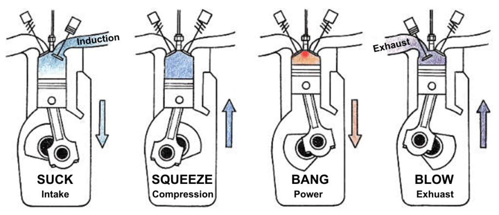
An Otto-cycle engine employs an operating cycle composed of four strokes, with each successive stroke associated with a different phase of the cycle. The four phases are usually referred to as intake, compression, power, and exhaust—or colloquially, suck, squeeze, bang, and blow:
SUCK: During the intake stroke, the piston moves away from the cylinder head with the intake valve open, creating a partial vacuum that sucks a combustible mixture (in our case, air containing atomized gasoline droplets) into the cylinder.
SQUEEZE: During the compression stroke, the piston moves toward the cylinder head with both valves closed, compressing the air-fuel charge into a much smaller volume, increasing its pressure and temperature, and making it more capable of combustion. The difference in volume of air-fuel charge between the start of the compression stroke (piston all the way down) and the end of the compression stroke (piston all the way up) is termed the “compression ratio.” Most aircraft engines have very conservative compression ratios (between 7:1 and 8.5:1); automotive engines usually have compression ratios between 8:1 and 10:1, racing engines up to 12:1, and Diesel engines 14:1 or more. The greater the compression ratio, the more efficient the engine at converting chemical energy into mechanical energy. (Piston aircraft engines aren’t particularly efficient.)
BANG: During the power stroke, the air-fuel charge is ignited by an electrical spark (or by the heat of compression in Diesel engines). Both valves remain closed, so the rapidly increasing pressure of the burning air-fuel charge drives the piston forcefully away from the cylinder head, converting chemical energy to mechanical energy. As the piston moves down in the cylinder and the volume of the air-fuel charge increases, its pressure and temperature decrease.
BLOW: During the exhaust stroke, the piston moves toward the cylinder head with the exhaust valve open, allowing what remains of the spent air-fuel charge to exit the cylinder and be expelled through the exhaust system. Because piston aircraft engines are not very efficient, substantial energy remains in the exhaust gas as it exits the cylinder. In a normally-aspirated engine, this energy is simply wasted; in a turbocharged engine, some of the energy is used to spin a compressor and raise the pressure of the engine’s induction air, allowing the engine to produce more power (especially at altitude).
The more, the merrier smoother
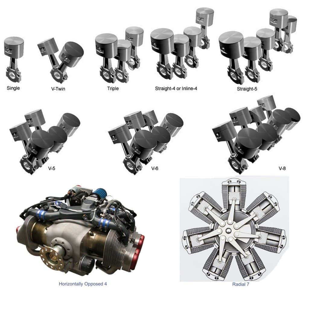
While the Otto cycle defines what’s going on within a single cylinder assembly, most piston engines have more than one cylinder. That’s because a fundamental limitation of the Otto cycle is that it only produces power 25% of the time. Consequently, the one-cylinder Otto-cycle engines commonly used on lawnmowers and small motorcycles tend to leave a lot to be desired in the smoothness and vibration departments.
The obvious solution is to have four cylinders arranged so that one is always in its power stroke at any given time; this approach results in a much smoother-running engine with far less vibration. Even greater smoothness is possible by adding additional cylinders and sequencing them so that one power stroke begins before the previous one finishes.

Numerous cylinder arrangements have been tried. Most automotive engines use either in-line (straight) or V-type layouts (for compactness), while most aircraft engines use either horizontally opposed or radial layouts (for improved air cooling). The most common configurations in piston-powered GA engines are 4 or 6 cylinders horizontally opposed.
Pressure and volume
Although the four-stroke Otto cycle is conceptually simple, what actually takes place inside the cylinder during each cycle is remarkably complex, as are the critical timing relationships of piston position, pressure, temperature, valve opening and closing, and ignition. The more you understand about the combustion event and timing relationships, the better job you will be able to do of managing your powerplant, optimizing your power and mixture settings, and troubleshooting any engine problems that may arise. With that in mind, let’s explore the Otto cycle a bit more deeply.

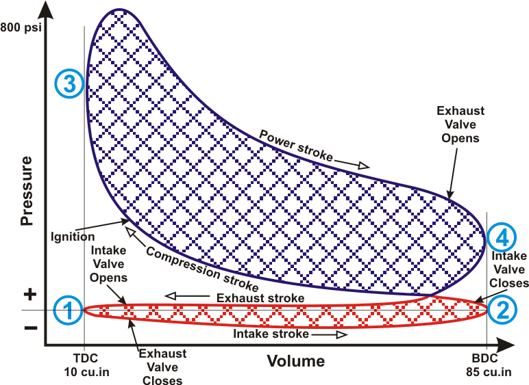
An excellent tool for visualizing what goes on during the Otto cycle is a “P-V diagram” that plots combustion chamber pressure and volume. Look at Figure 3 and let’s work through the four strokes of the Otto cycle:
SUCK: Beginning at point (1) on the diagram, the piston starts at the top of its travel (“top dead center” or TDC) and moves to the bottom of its travel (“bottom dead center” or BDC). The intake valve is fully open, the exhaust valve closes, and the descending piston creates suction that draws the air-fuel charge into the cylinder.
SQUEEZE: At point (2), the piston reverses direction and moves from BDC to TDC. The intake valve closes, and the air-fuel charge is compressed—for example, from a volume of 85 cu.in. to 10 cu.in. (a compression ratio of 8.5:1)—causing the pressure and temperature in the combustion chamber to rise accordingly. As the piston approaches TDC—typically 20° to 24° of crankshaft rotation before it gets there—the ignition system fires the spark plugs, and the air-fuel charge starts to burn, causing the pressure and temperature to increase even faster.
BANG: At point (3), the piston reaches TDC and reverses direction again, moving toward BDC. Meantime, the combustion of the air-fuel charge accelerates, reaching a maximum pressure and temperature at about 15° to 20° of crankshaft rotation after TDC. This is the point of peak internal combustion pressure (ICP), which is typically 800 psi in a normally aspirated engine and as much as 1,000 psi in a turbocharged engine. This high pressure pushes the piston down towards BDC rather forcefully: 800 psi pressing on a 5¼-inch piston produces more than 17,000 pounds of force. As the piston descends and the air-fuel charge expands, its pressure and temperature drop considerably as chemical energy is converted to mechanical energy. Shortly before the piston reaches BDC, the exhaust valve starts to open. Since the pressure in the cylinder is still considerably greater than outside ambient, exhaust gas starts flowing out the exhaust valve into the exhaust system in a process termed “blowdown.”
BLOW: At point (4), the piston reaches BDC and reverses direction once more, moving toward TDC. As the piston rises, it compresses the remaining fuel-air charge and forces it out the exhaust valve. Shortly before the piston reaches TDC, the intake valve starts to open, so that it can be fully open by the time the piston reaches point (1) and reverses direction to start the intake stroke. The brief period during which both intake and exhaust valves are open here is known as the “valve overlap interval.”
Because of their low compression ratios, spark-ignition piston aircraft engines are unusually inefficient as Otto-cycle engines go. They typically convert only about one-third of the fuel’s chemical energy to mechanical energy, and waste about one-half of it out the exhaust and the remaining one-sixth in radiated energy from cylinder fins and oil cooler. The EPA-mandated move to unleaded avgas won’t help this one bit. Diesel engines with their much higher compression ratios represent our best hope for more efficient piston aircraft engines in the future.
You bought a plane to fly it, not stress over maintenance.
At Savvy Aviation, we believe you shouldn’t have to navigate the complexities of aircraft maintenance alone. And you definitely shouldn’t be surprised when your shop’s invoice arrives.
Savvy Aviation isn’t a maintenance shop – we empower you with the knowledge and expert consultation you need to be in control of your own maintenance events – so your shop takes directives (not gives them). Whatever your maintenance needs, Savvy has a perfect plan for you: