by Paul Kortopates
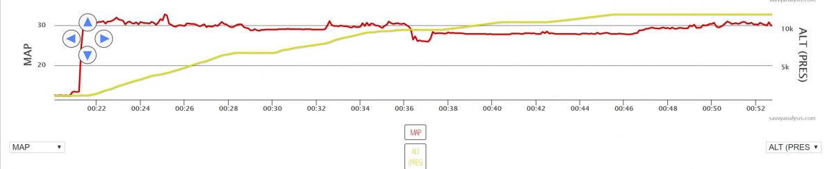
One of the more common turbo problems we see are erratic fluctuations in MAP. Below is a plot of MAP (the red trace) & Altitude (the yellow trace) of a Cirrus. Although the data is a bit coarse with a 6 sec data sampling rate, when zoomed in we could see MAP fluctuations as large as 2.5”.
Looking at some recent past data in the next figure that shows MAP data from takeoff to 15,000’, we can see prior MAP data is actually quite stable as we would expect.
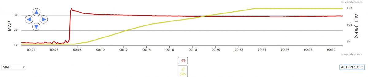
The engine data we’re looking at above is from Tornado Alley SR22 Turbo Normalized IO-550. The SR22 TAT Turbo Normalizing System is diagramed in the next figure below, and consists of dual turbo chargers and dual wastegate actuators controlled by a single absolute pressure controller regulator.
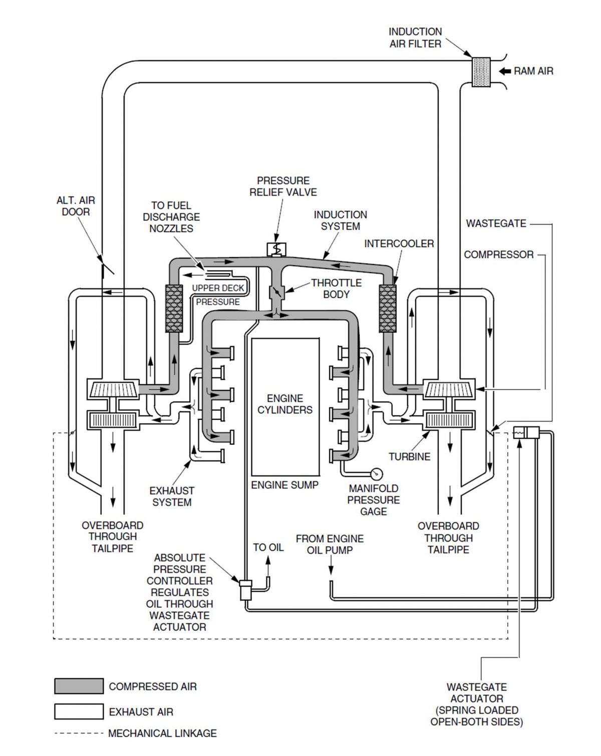
The absolute pressure controller (APC) continually monitors the turbocharger’s compressor output, also known as “upper deck pressure” (UDP) and regulates it through the wastegate. The APC attempts to maintain a constant UDP by controlling the two wastegate actuators. The wastegate actuators have a butterfly, much like a throttle butterfly, to control the amount of exhaust gas that is allowed to bypass the turbocharger. It is normally held in the full-open position by a spring which allows all exhaust gas to bypass. But as the controller applies regulated engine oil pressure to the wastegate, it causes the wastegate butterfly to close down against the spring tension and forces exhaust gas to go through the turbo charger. In our specific TAT installation the one APC controls the master wastegate hydraulically on the right hand side of the engine. The master wastegate in turn has a mechanical linkage to a slave wastegate on the left hand side that moves the slave to the same setting as the master actuator.
The controllers are fairly simple devices consisting of aneroid bellows for sensing pressure and a poppet valve to vary the oil pressure to the wastegate and maintain the controllers “set-point” for UDP. So although either the controller, including sensing lines, or the wastegate could all result in the MAP fluctuation we tend to see the wastegate actuators as more commonly the culprit. The wastegate actuators operate in the worst environment, and are subject to the heat and deposits of the exhaust. All this works against actuators longevity and ability to regulate with any precision.
Given the MAP fluctuations we suggested to our client to have his mechanic to start with checking both his wastegates for any issues including the common sticky gates from too much exhaust deposits. His tech indeed found an issue with the linkage to the slave wastegate actuator and pulled it for repair/replacement. So what can we do to avoid this as pilot/owners? Over time wastegate stickiness is unavoidable but the best practice to minimize occurrence is to liberally lubricate the shaft of your wastegate(s) with mouse milk oil with every oil change. It helps to put a wrench on the wastegate shaft and work the gate against the spring to work in the mouse milk and loosen up exhaust deposits.
Another common turbo problem we see is low max fuel flow on takeoff which can very insidious to the pilot. In earlier models this is almost always accompanied with higher than expected CHTs simply because the older or legacy aircraft baffling wasn’t that great to begin with. But in the newer production aircraft where baffling has been greatly improved high CHT is not as often an additional clue requiring us to pay attention to TIT and Fuel Flow (FF) on takeoff. Below is an example of very low max FF at full power which resulted in power loss at takeoff as well as an escalating CHT3 as FF dropped even more while MAP and RPM stayed constant.
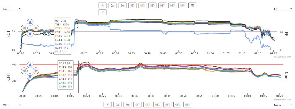
The plot above is from a Mooney where we expect to see Max FF in the TCM specified range of 21.3-23.0 GPH, but we prefer and advise to target for 1 GPH above the high number of 23 for 24 GPH. But the FF on this takeoff is only 17.4 GPH which is dangerously low. There are two helpful clues that all of us turbo operators should be looking at during the takeoff run, TIT and FF, knowing you max takeoff FF can help you prevent taking off in this situation as well as high TIT on takeoff. What is high TIT on takeoff? Unfortunately, most older POH’s don’t even address this but modern POH’s do a much better job with many calling for turning on the boost pump if TIT gets to 1450F or above. The boost pump can help drive FF up to where it should be and get TIT back down before further risk of detonation and/or escalating CHTs.
So with all this consideration of avoiding too low of FF on takeoff, what about too high of FF on takeoff? Too high of a FF will rob us of power too. Its not as common as low max FF on takeoff but we see overly high FF on takeoff too. Again the clue lies in TIT and FF on takeoff.
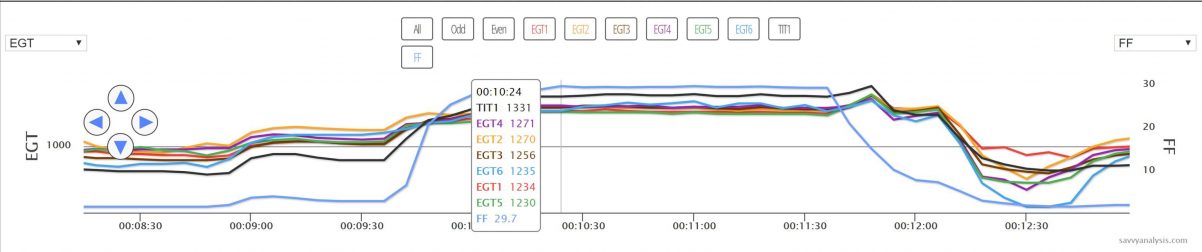
The data above is also from a Mooney 252 with the TSIO-360-MB engine but here we’re seeing max FF of 29.7 GPH which is nearly 6 GPH above our target value of 24. The pilot experienced a partial power loss on takeoff (not shown is a drop of nearly 200 rpm and MAP fluctuation when the FF hits its max as shown above). We advised the owner to get the max FF adjusted back into TCM specifications. While the owner was trying to get the fuel pump set up corrected the tech found it couldn’t be adjusted to within spec and pulled it for repair. The repair shop reported: ”The pump apparently had developed a “gaping” hole in a pressure diaphragm, and that is what caused the problem…” This Mooney’s max FF had been going up higher and higher over the past several flights as the diaphragm was getting more ruptured. But once again the big clues for us are TIT and FF, but although TIT is certainly depressed from the being overly rich, it’s the high FF that is the most obvious clue to signal us that we have an issue on takeoff. Therein lies the value of knowing and monitoring your normal max power takeoff TIT and FF, in addition to redline MAP and RPM on every takeoff.
