Pilots think of ground effect as the reduced aerodynamic drag that happens under the wing to cushion a landing or help with a short-field takeoff. Analysts, who are also all pilots by the way, think of it as what happens when a poor ground connection for an engine data monitor interferes with collecting the data. What’s to be gained by looking at crummy, unreliable data? If you saw these indications in the air they’d be unsettling. If you saw them while reviewing the data after the flight you’d be tempted to put the airplane in the shop.
But what do you tell the shop? Replace all the probes? That might be an expensive trip to nowhere, since you would spend a lot of money and not solve the problem. So let’s review some data and determine if they are ground issues or not, so if you see a pattern like this you can take the appropriate next steps.
Let’s start with data from a Cub Crafters Carbon Cub with an ECi 340 engine and data from an EI CGR-30p with a 1 sec sample rate. The client submitted a flight and when we opened it we saw this.
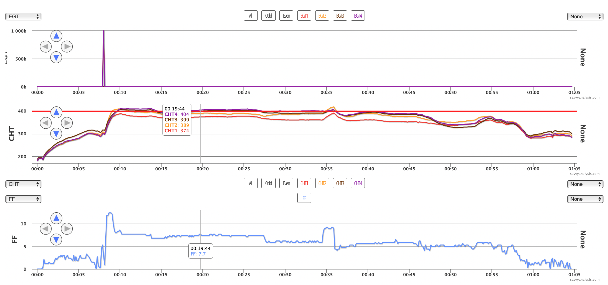
It looks like the engine is running – CHTs and FF look normal – but EGTs look anything but normal. Here’s why –
Our Y scale adjusts to the values it has to display. At the 8 min mark there’s an EGT spike in 2 and 4 to some impossible six-digit number. That’s causing all the other – normal – values to get squished into what looks like a flat line.
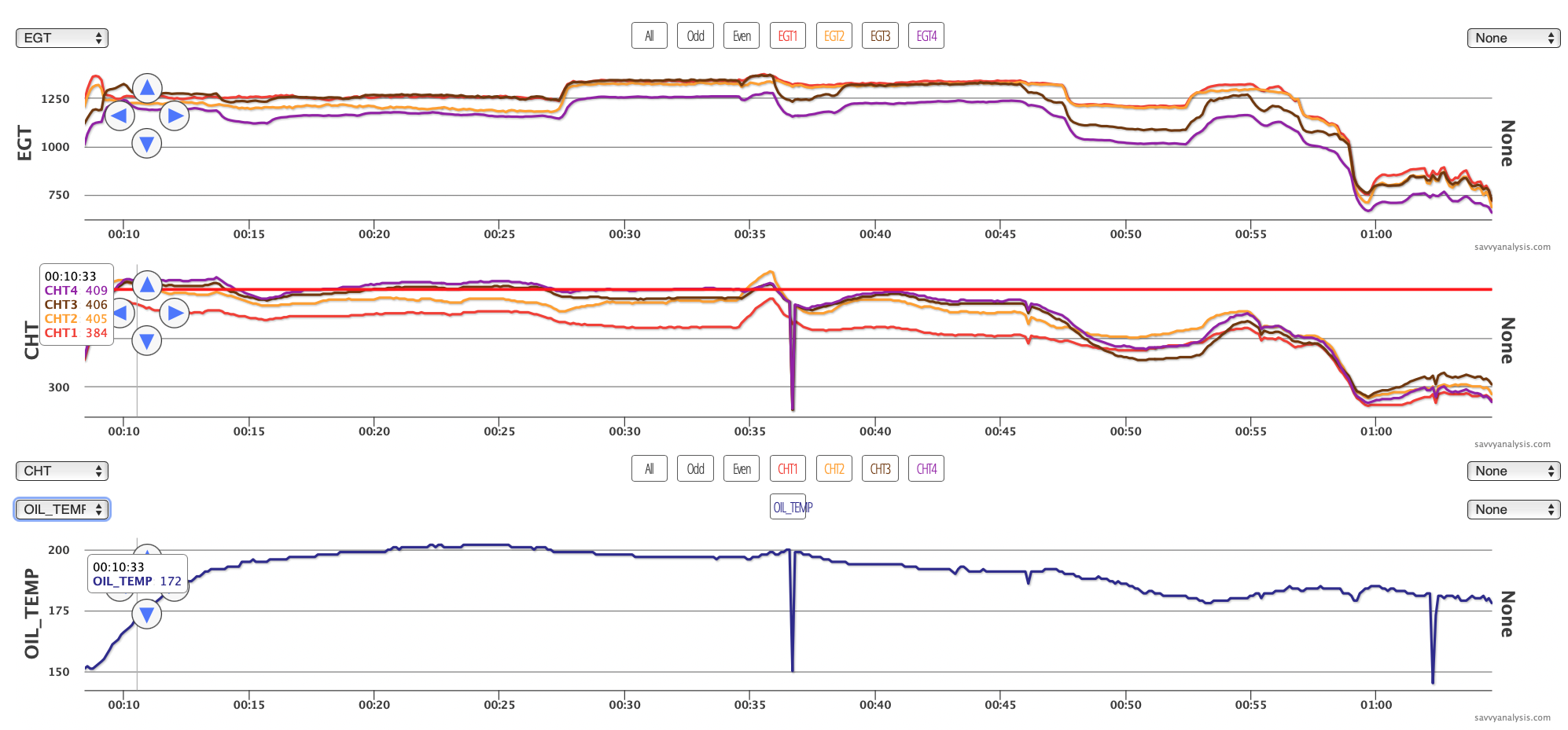
If you zoom into (click and drag) the data after the spike you’ll see normal values until everything spikes at the 36 min mark. And there’s an oil temp spike near the end of the flight.
Correction – almost everything spikes at 36 mins. CHT 1 doesn’t. Here’s that spike with values.
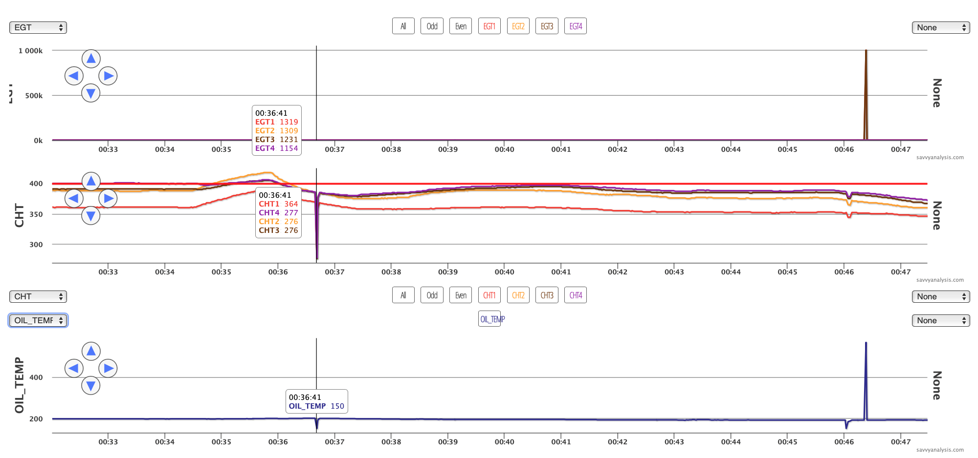
The rule of thumb is that when all values drop or spike, it’s a grounding problem. But when some – not all – values drop or spike, it could be connections at the back of the unit, or maybe at the firewall.
Mark Colman is one of Savvy’s avionics specialists, and offers these tips when working with grounding problems.
JPI engine monitors do need a separate ground run to the engine, or the display sparkles….or just jumps around.
Insight engine monitors need a ferrite installed on the harness or they do the same thing.
I can test for a bad ground strap bonding by setting a voltmeter to volts DC, one lead on the engine, the other on the firewall. Then crank the starter. If I read anything over about 0.100 volts, the bonding strap is not well. I have seen around 5v on bad straps or connection points.
Next up is data from a Cirrus SR20 with a Continental IO-360 engine and data from an Avidyne with a 6 sec sample rate. This is a ground run to gather data. We know because max FF is just over 5 GPH.
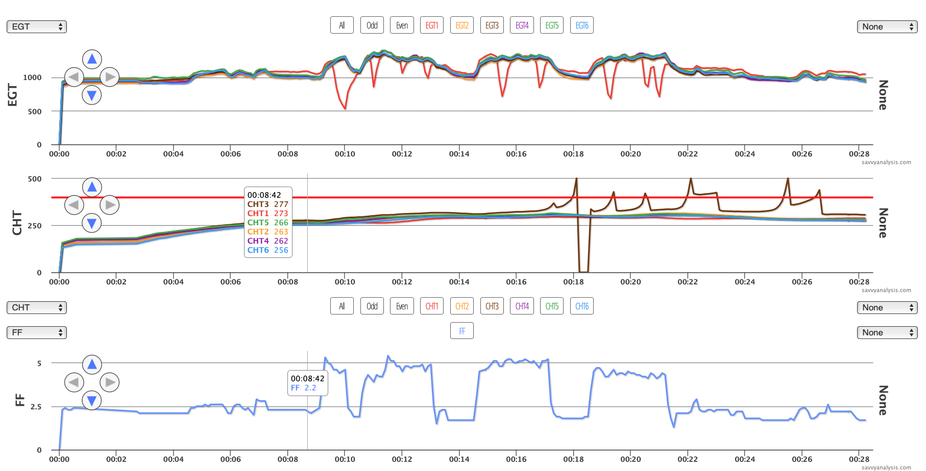
What can we trust and what’s bogus? The drops in EGT 1 – the red trace – look real. They happen at the higher FF settings, and if you look closely, after a quick rise in EGT 1 just before the drop. CHT 1 doesn’t really corroborate it, but we know CHTs move like snails compared to the hummingbird speed of EGTs, and the red CHT 1 traces do move to the bottom of the ribbon after each EGT drop. This is probably an injector clog that can process FF at idle, then chokes out at 5 GPH.
CHT 3, on the other hand, is the kind of data that makes Penn & Teller yell “Bullsh*t!.” A cylinder can’t spike to 500 then drop immediately to zero. This data was gathered to verify something the pilot observed – that when CHT 3 started to rise, he could stop the rise by turning on the fuel pump. Maybe you’re thinking “sure, more fuel cools it down.” Except FF isn’t changing, not much anyway. But the pump is going on and off.
Our client did some detective work. He reported “I traced the CHT wiring upstream from the cylinder. It plugs into the MCU130, with one wire connector plug between the two (housed in a protective sleeve). Further upstream from this connector plug it joins a bigger bundle of wires that includes the fuel pump wiring. This is the only interaction between the fuel pump and CHT probe wiring that is obvious.” And he added “The connectors were checked during the last annual when the CHT probe was replaced (and confirmed they are the Cirrus improved connectors, post SB 2x-77-02-R2). Stabilant was applied. No improvement.”
Savvy’s technical director Jeff Iskierka has an encyclopedic knowledge of Cirrus electrical systems. He offered this —
“The boost pump , oat, and SIU/DAU share the 602 ground block on inside firewall. Forward of copilot feet. This comes thru to the engine side firewall. Then to engine etc. Need to look at grounds.
Kind of odd it’s just one. Deeper troubleshooting might get deep. Might pick the easy firewall connector, open it up, extract pins and swap with CHT that is steady. This isolated firewall forward or behind firewall. I am talking about the feed wires not the grounds now. The same can be done at the SIU/DAU.
Running battery dead has damaged the DAUs in the past.
Older planes had short harness to the SIU and some wire harnesses chaffed at the back of radio rack.
The clue that this wasn’t just a failing probe was the observation that it was tied to the fuel pump. We’re glad we had the resources of the entire Savvy team to solve this one.
Next up is data from an older Bonanza 35 with a Continental IO-520 and data from an Insight G4 with a 1 sec sample rate. I have added oil temp to this one. I put the cursor full left just to keep it out of the way.
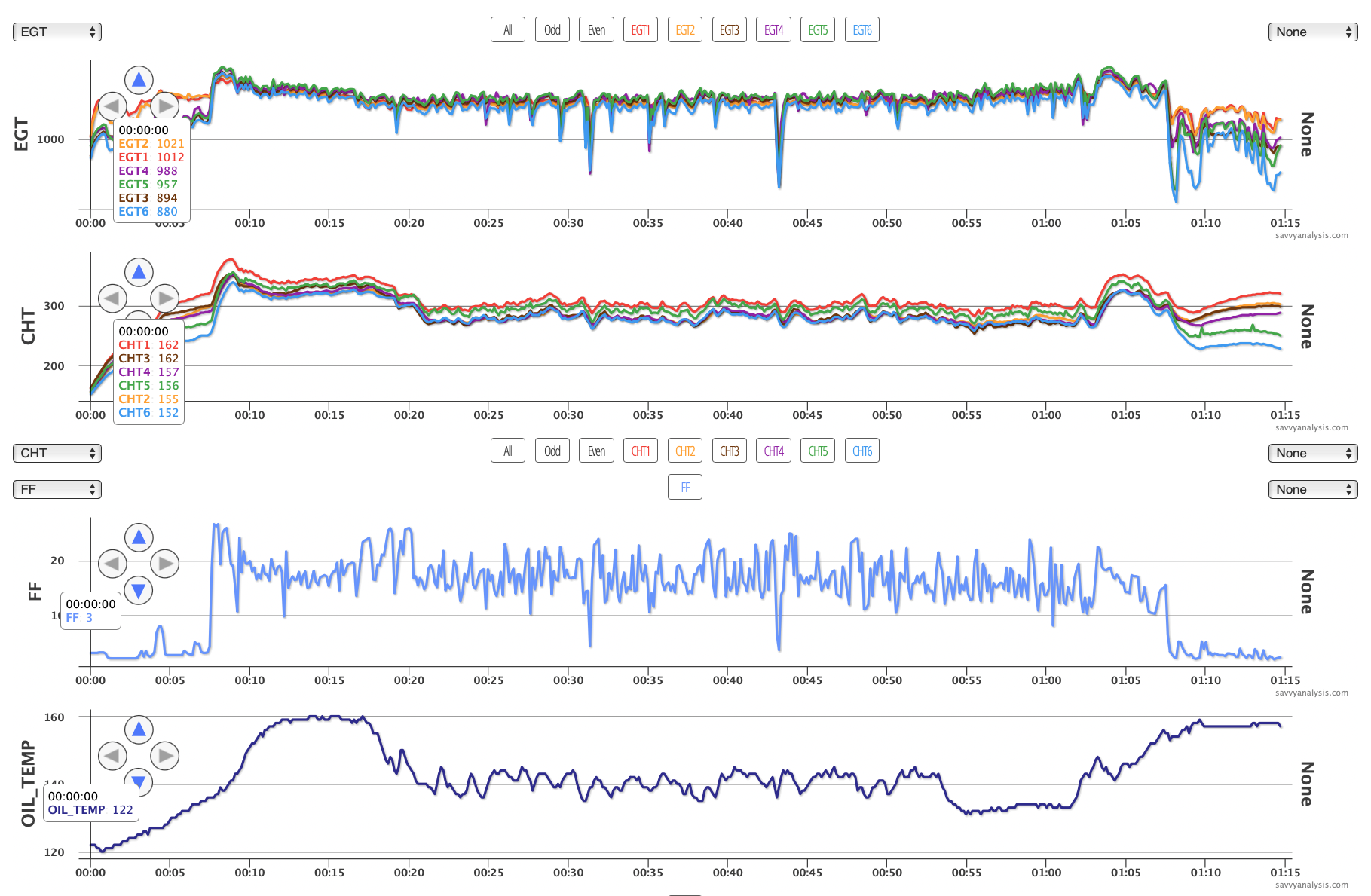
Sometimes the data is so bad that you wonder if you’d be better off putting one of those rubber soap holders over the display like we used to do with failed gyro instruments. The good news is the data is steadier during ground ops. And a little less noisy during initial climb. In a case like this, changing out one or two sensors or probes is unlikely to have any impact. Time is better spent checking wires and connections that would apply to all the sensors, or maybe the grounding of the unit itself.
