We’ve seen an increase in issues related to induction lately. Is it because many airplanes spent more time grounded because of the virus, and issues are emerging as the hibernation is ending? Or maybe it’s just that for most of our US-based clients, temperatures are warming and taking their toll on clamps, sleeves and gaskets. Whatever the reason, we’ll spend this month looking at what’s different about data from induction leaks. It’s tempting to drift into the mechanics of an induction leak, but I’ll stick to how to spot it in the data. John Deakin, Mike Busch and others have written extensively on plumbing, Bernoulli and Venturi if that’s what you’re after.
I’ll drift this far – when your MAP gauge is showing 12″ at idle, and ambient pressure is around 29″, your gauge is measuring suction. More accurately, it’s measuring how much of that ambient pressure it’s keeping out of the engine. Knowing that, and before looking at any data, what if we see idle MAP up around 16-17″? It means that for a normally aspirated engine – carb or injectors – air is getting past the closed throttle plate and into the engine. What about turbos? At idle, the turbo’s influence on induction should be minimal. If idle MAP is high, either the turbo is kicking in when it shouldn’t, or air is getting in through a leak.
Those are the clues at idle. At takeoff, MAP and ambient pressure should be close. MAP will always be about an inch lower because of the inefficiencies of the air filter and the intake plumbing. But that air filter gives you a lot of engine longevity for that inch – it’s a good trade. Even up high at WOT, MAP and ambient pressure should be close – except for turbos. That should be enough theory to get us started. Let’s look at data.
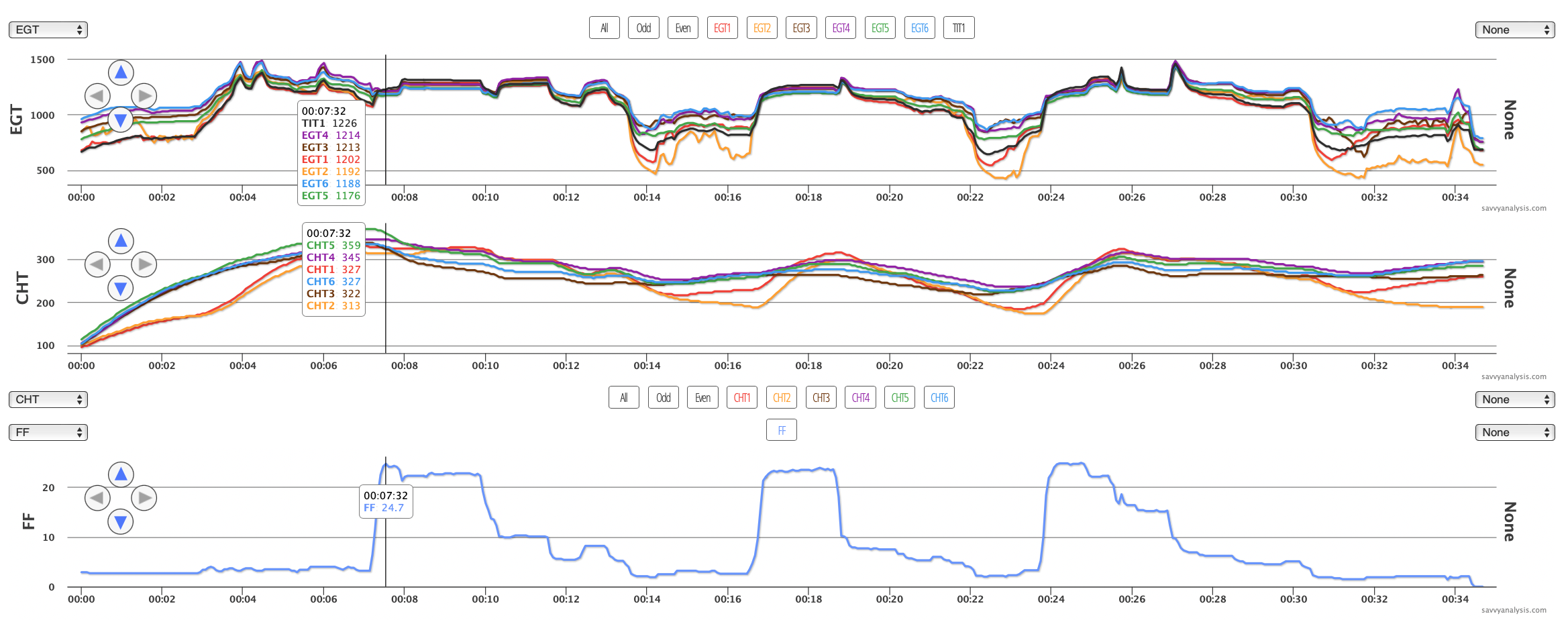
First up is a Cessna 182 with a Continental O-470 and data from a JPI 730 with a 2 sec sample rate. EGTs, CHTs and FF.
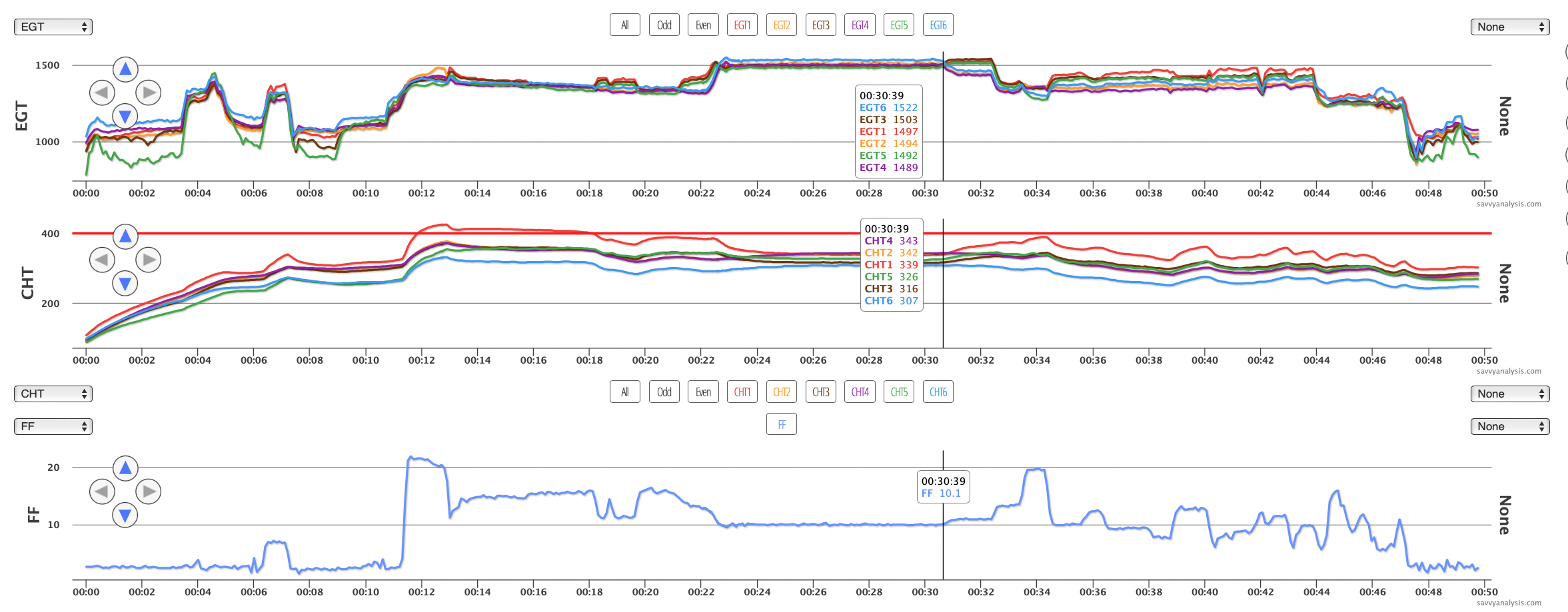
Several anomalies here, but the notable ones are EGTs 5 and 3 during idle, EGTs 1-3-5 acting different from 2-4-6 at the 21 min mark and again just right of the cursor. Both times they react of changes in FF. Let’s use that drop in FF at 21 mins as a GAMI sweep. Switching to GAMI mode and zooming in.
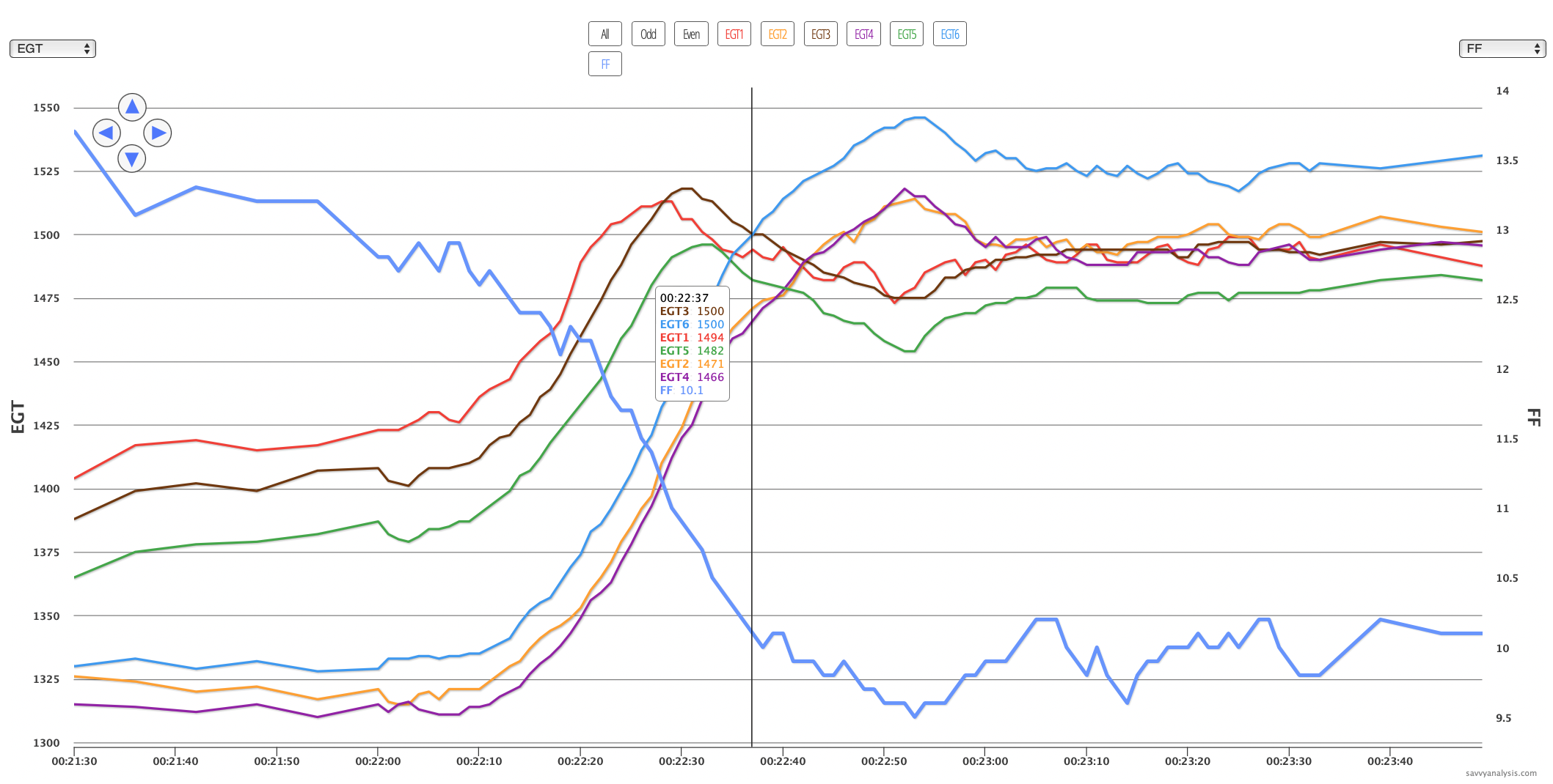
When 1-3-5 peak much earlier than 2-4-6, and (obviously) MAP, RPMs and FF are the same for both sides, that’s a pretty smoking gun for an induction leak. Let’s look at EGTs and MAP at idle and see if there was a clue.
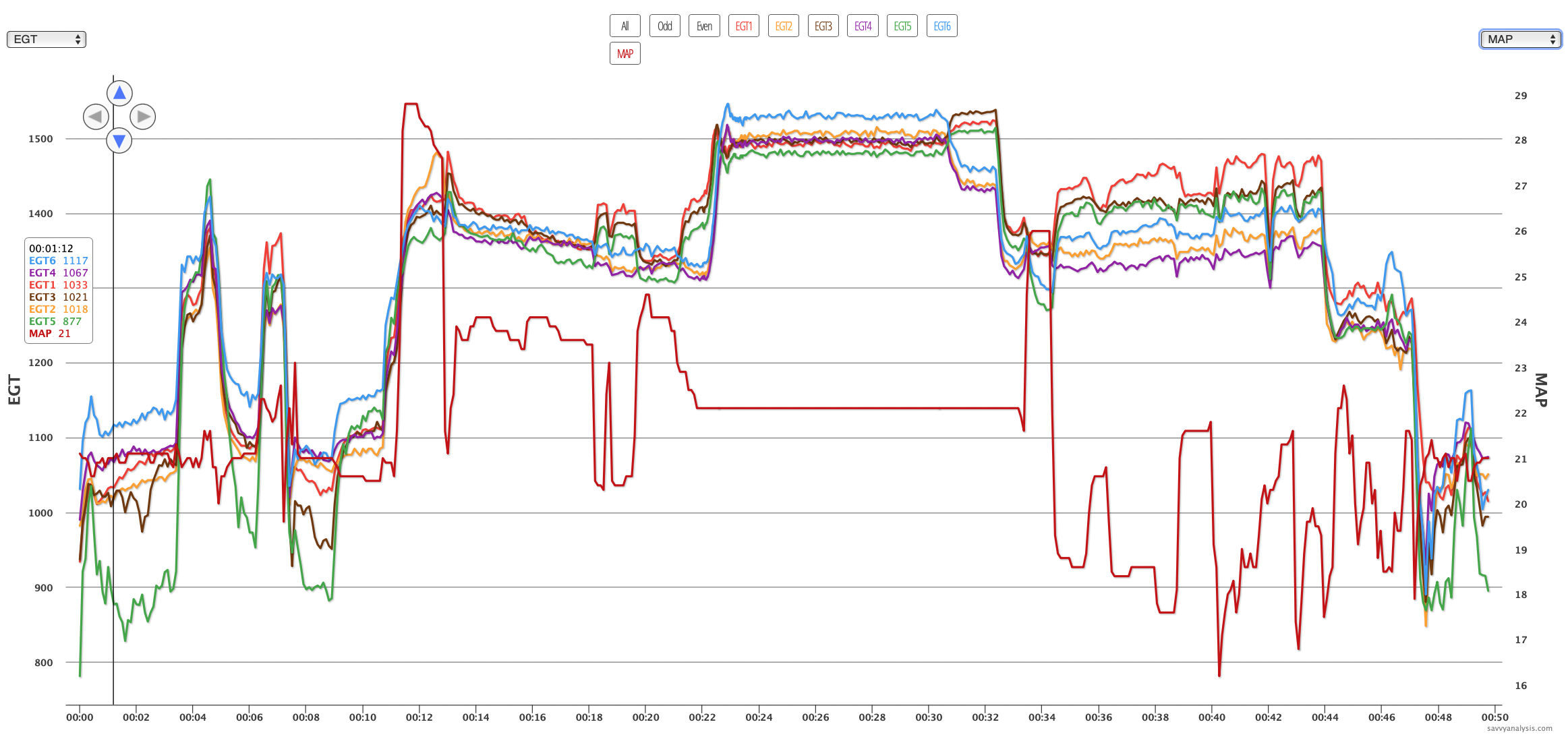
MAP of 21″ is another smoking gun. Notice at 31 mins the two banks of cylinders diverge but MAP is steady. Back to the first chart, there’s a slight increase in FF there. More gas should bring EGTs down like we see in 2-4-6, unless they’re already running very lean, as 1-3-5 are.
Before we leave carbs, a quick shoutout to carb heat and its role in shuffling the deck to disrupt induction air. Applying partial carb heat should move all the EGTs in the same direction. If it moves some more than others, that’s a clue that there’s a leak in the system.
Here’s data from a Bonanza 35 with a Continental IO-470 and data from an Insight G4 with a 1 sec sample rate. EGT’s, CHTs, then FF and MAP together.
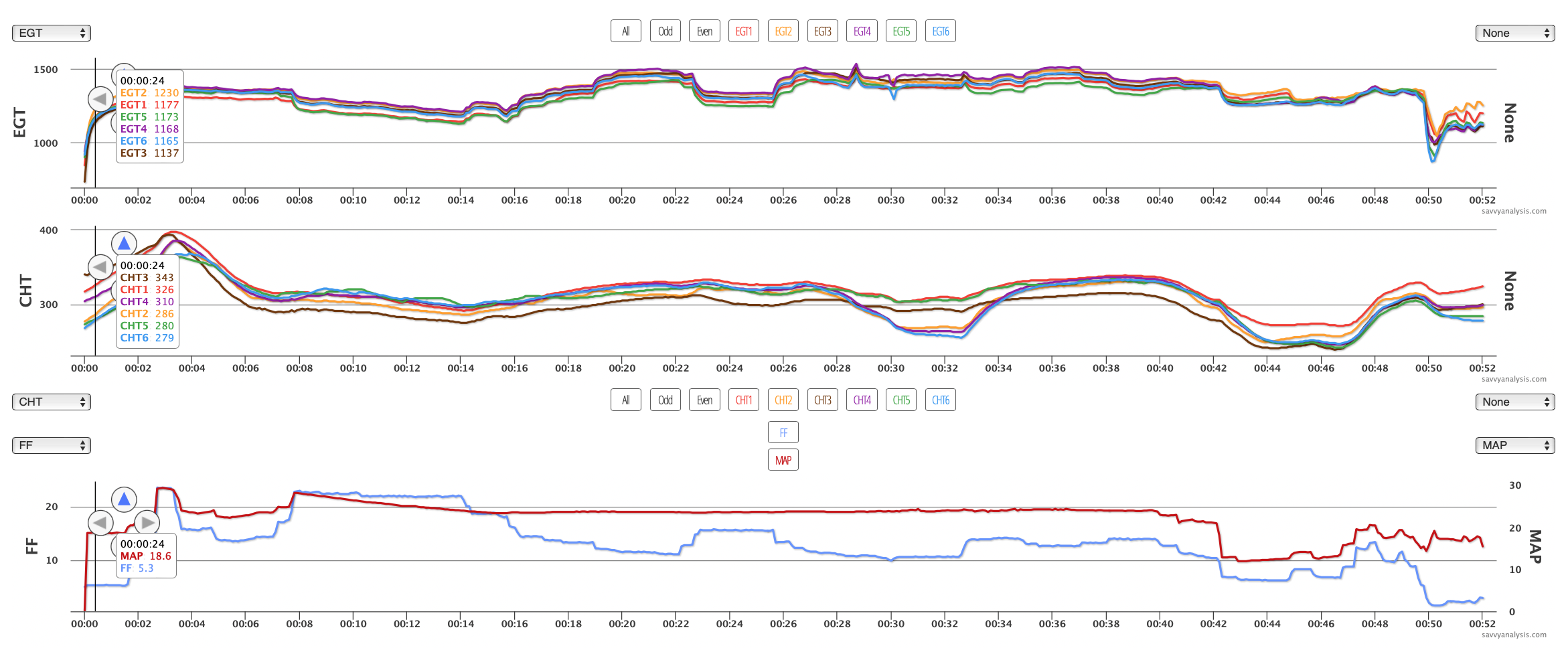
Even without zooming in, you can see that there are spots where 1-3-5 and 2-4-6 move independently. Idle MAP is 18.6″ so we recommended checking for a leak and the client discovered the intake clamp for the #2 cyl was out of place.
Here’s data from a Mooney M20K with a 231 Aftercooler mod on the Continental TSIO-360 engine with data from a JPI 830 with a 2 sec sample rate. EGTs, CHTs and FF.
This ticket arrived with a report of the engine shaking at idle. It’s pretty clear that something’s going on with cyl 2. Cyl 1 sometimes tags along, but 2 looks like the bigger problem. What can idle MAP tell us? — remember this is a turbo.
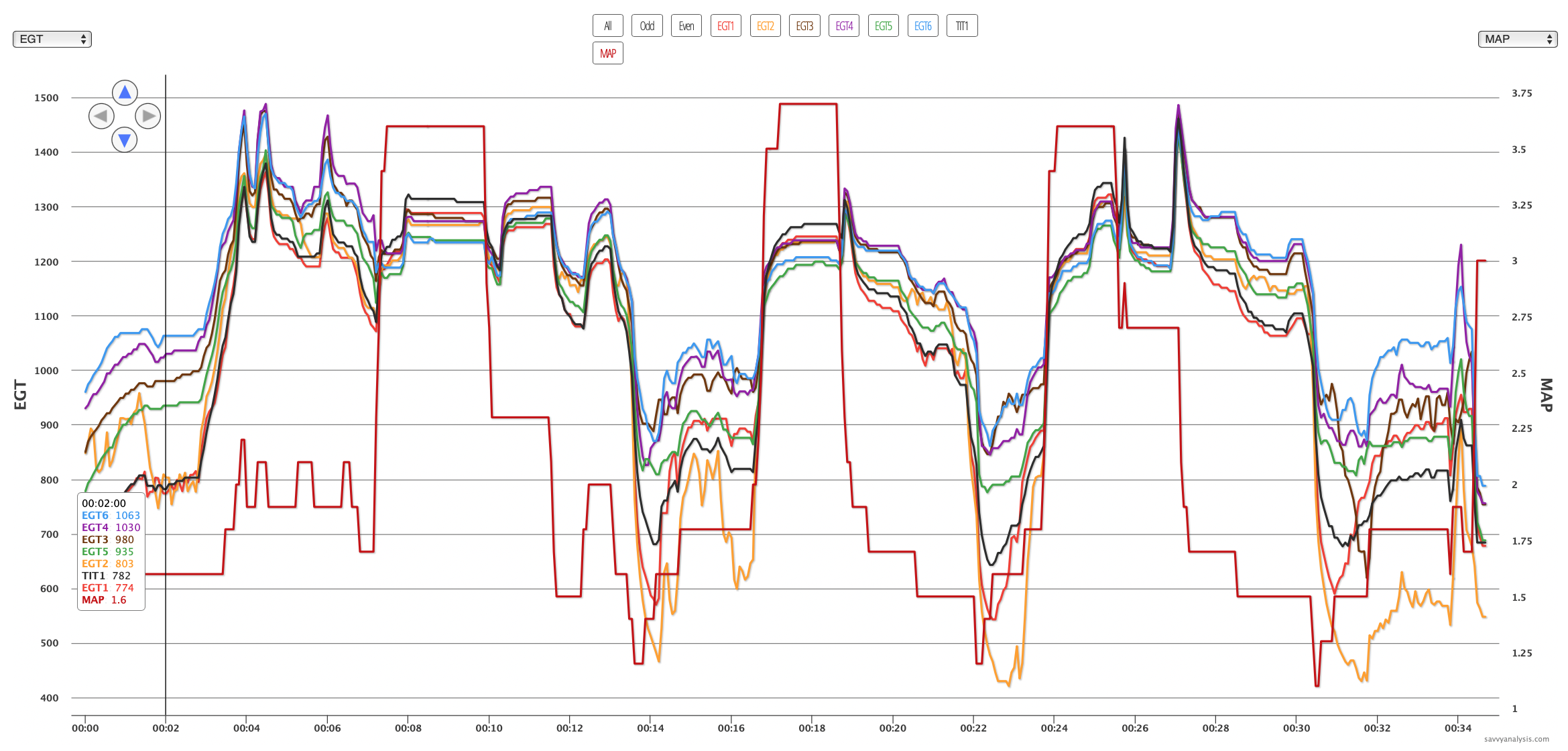
Hmm, we didn’t see that coming. Idle MAP shows 1.6″ and max MAP shows 3.7″. If we move the decimal point, we get 16″ at idle and 37″ max – that’s more like it. Even if that decimal SWAG isn’t completely reliable, it suggests that idle MAP is higher than we want it. We recommended checking induction and the client reported “The hose clamp had fallen off at the front end of the hose attaching the left intake header to the Y.” All fixed now. And the JPI will get a firmware update that should correct the decimal on MAP.
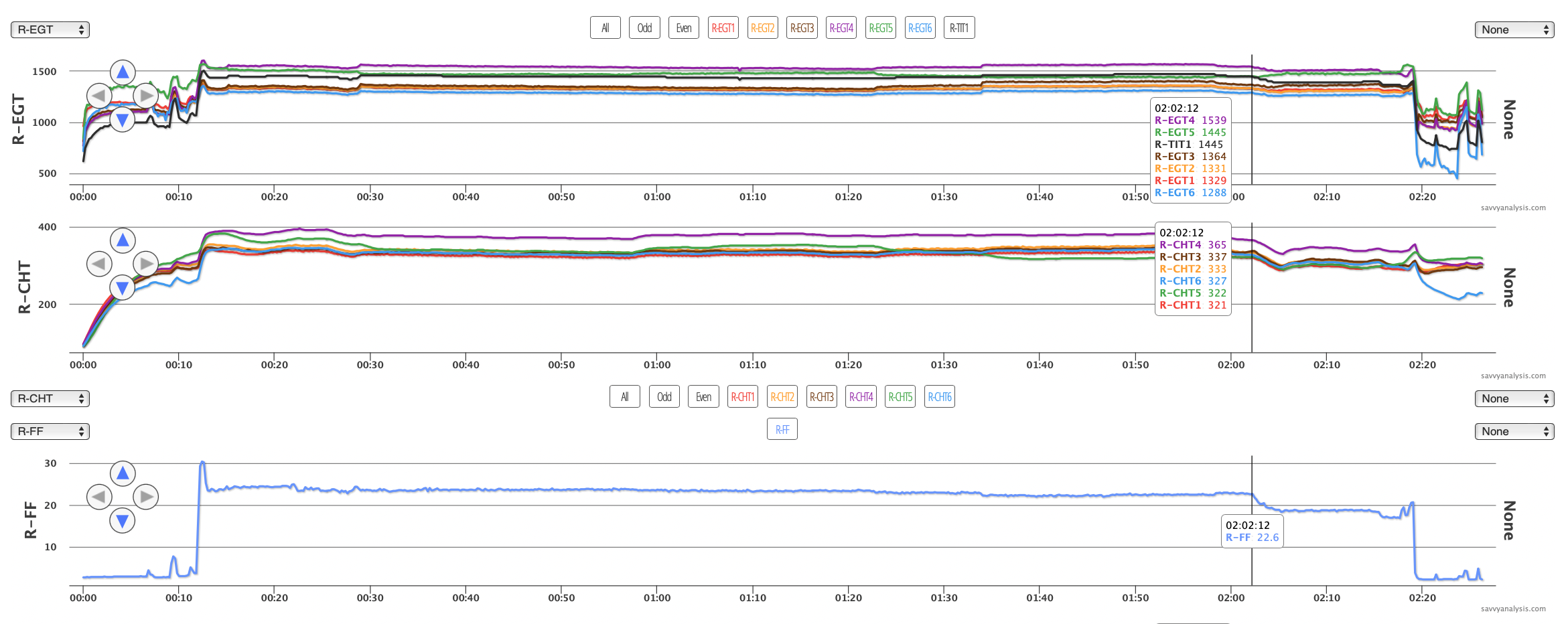
We’ll end this month with data from the right engine of a Cessna 340 with Continental TSIO-520 engines and data from a JPI 960 with a 6 sec sample rate. EGT, CHT and FF.
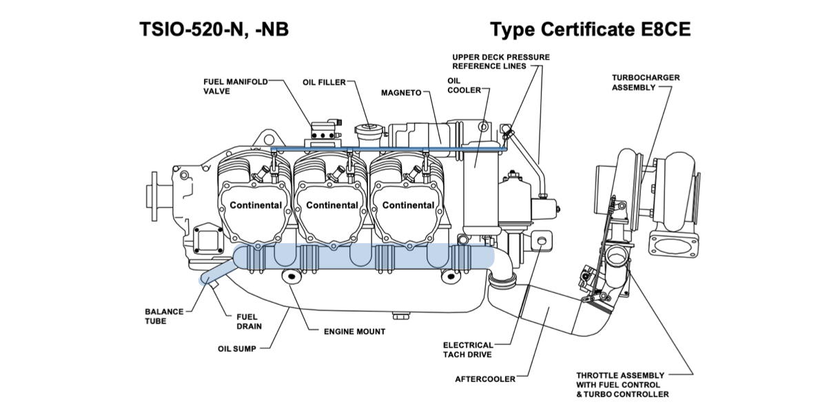
In case you’re not familiar with induction on a turbo, here’s a crib sheet with induction highlighted in blue. There are the big tubes with clamps and sleeves under the cylinders – same as a normally aspirated engine – plus there’s an upper deck reference line, which can be a source of induction leaks.
Back to the 340, we noticed that EGT and CHT 4 are high throughout, even as FF changes. Quickly running through the options, high EGT and low or normal CHT is a symptom of a bad plug. High EGT and CHT at max FF, then both moving lower as FF is reduced is a symptom of an injector clog. High EGT and CHT throughout suggests induction. Upon checking, our client discovered “the sleeve assembly nut connecting to the upper deck line was loose on cylinder 4.”
